Authors: Ayad Shammout & Denny Lee
Technical Reviewers: Lukasz Pawlowski, Sanjay Mishra, Prem Mehra, Michael Thomassy, Lindsey Allen, Burzin Patel, Andy Wu, Thomas Kejser, Carl Rabeler, Quoc Bui
Applies to: SQL Server 2005, SQL Server 2008
Introduction
There are many ways to perform disaster recovery with Microsoft SQL Server Reporting Services (SSRS). Based upon customer experience and internal testing, this technical note provides guidance around best practices to design and manage robust end-to-end disaster recovery (DR). This DR method will involve both automatic and manual failover in the form of content switches, SQL Server failover clustering, and database mirroring. This case study focuses on the lessons learned from CareGroup Healthcare System.
Environment Setup
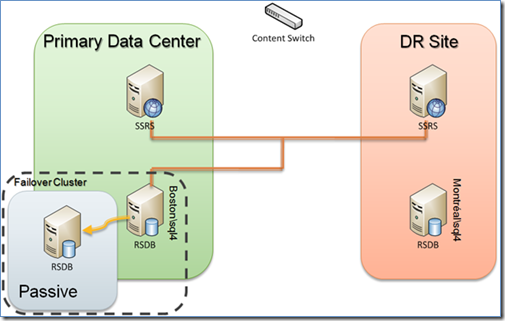
Figure 1 shows a basic disaster recovery scenario. The left side (in green) represents the primary data center, while the right side (in orange) represents the disaster recovery (DR) site. In general the two sites should be identical or at least very similar to each other so that the DR site will be able to handle the load of the primary data center; all of this should be transparent to the users.

Figure 1: Primary data center and the disaster recovery site
Primary Data Center
The primary data center contains the Reporting Services Web service servers (there is only one for the purpose of this diagram); the report catalogs are placed on a separate server (RSDB). As a general rule, you should set up the report catalogs (RSDB) in a failover cluster, because the report catalogs are central to the Reporting Services environment.
Disaster Recovery Site
The disaster recovery site should closely duplicate the primary data center Reporting Services environment. It should be located in another geographic location such that if the primary data center experiences a resource disruption (for example, in connectivity or power), all traffic can be redirected to the alternate site with minimal disruption to service. In noncritical scenarios, you can utilize fewer resources (for example, less powerful servers, fewer servers) but for mission-critical systems, we highly recommend a server-for-server duplication of resources.
Network Setup
To ensure connectivity from the clients to the primary data center and the disaster recovery site, a common technique is to use a content switch to load-balance traffic within the individual sites as well as between the global sites. In the case of CareGroup Healthcare, a Cisco GSS is used as the content switch. As well, there is direct fiber network connectivity between the primary data center and the disaster recovery site to ensure minimal latencies for any communication between the two centers. If the primary site goes down for any reason, the content switch transparently redirects all client traffic to the disaster recovery set of Reporting Services servers. If the content switch is unavailable, the IP address can be changed at the DNS level. This latter change is a manual switch with a slightly longer network outage, which is due to the DNS cache clearing the old IP address and pointing to the new one.
Database Setup
For the CareGroup Healthcare environment, the primary RSDB instance within the primary data center is named Boston\sql4 and is a SQL Server cluster using SQL Server 2008 Enterprise, with the content switch pointing to the alias sql4. An active/passive failover cluster is used; this allows other active database instances to be located on the server in the passive node. This technique works well if the passive node is not overutilized such that it can handle the Reporting Services workload if the Reporting Services active node goes offline. It may make sense to go to an active/active cluster if there is enough traffic, concurrent users, and/or resources, though the discussion of the tradeoffs between idle machines and high availability scenarios is outside the scope of this technical note. Each of these clustering techniques has unique advantages; ultimately, it is important to ensure that the report catalogs are consistently running with minimal downtime. For more information about how to best configure a SQL Server clustering environment, see SQL Server 2008 Failover Clustering.
To ensure that the RSDB within the disaster recovery site is up-to-date, a common technique is to use asynchronous database mirroring. For the CareGroup Healthcare environment, the mirrored RSDB instance is named Montréal\sql4 and is a SQL Server cluster using SQL Server 2008 Enterprise. Note that while the domain names are different (Montréal vs. Boston in this case), the SQL Server clusters for the primary data center and the disaster recovery site have the same name (more on this later). The key database to keep in sync is the report server (RSDB) database, because it stores all of the report metadata, including report definitions, report history and snapshots, and scheduling information. All Reporting Services operations must connect to this database to access its metadata to perform their functions. The reason asynchronous database mirroring is commonly chosen is that asynchronous mirroring has minimal or no impact on response time performance. In addition, asynchronous mirroring works well because RSDB metadata is not frequently updated.
The following table describes an example endpoint setup for these database mirrors.

Initializing Database Mirror
A relatively easy way to initialize a database mirroring setup is to:
1) Make full and transaction log backups of the Reporting Services databases on the principal server.
2) Copy the backups over to the disaster recovery site, restoring each Reporting Services database in no-recovery mode.
3) Set up the failover partner on the mirror (that is, the DR site) before you set up the failover partner on the principal server.
Failover Scenarios
There are three main disaster recovery scenarios that can occur within this Reporting Services disaster recovery environment:
· Reporting Services servers within the primary data center go offline.
· The active server for the RSDB in the primary data center failover cluster goes offline.
· The entire cluster for the RSDB in the primary data center goes offline.
Please note that this note does not explicitly cover the scenarios concerning the Reporting Source databases. While most of the information here is applicable to these databases (such as data marts, operational data stores, transactional systems, and data warehouses), they have their own disaster recovery requirements and procedures that should be separate from the reporting infrastructure.
Reporting Services Servers within the Primary Data Center Go Offline
As noted in Figure 2, both Reporting Services servers point to the same cluster of databases. In this case, they both point to the active/passive database cluster Boston\sql4.

Figure 2: Reporting Services servers within the Primary Data Center go offline
In this scenario where the Reporting Services servers within the primary data center go offline, the hardware content switch will detect a network connectivity issue and automatically fail over to the disaster recovery site. By default, the Reporting Services farm connects to the report catalog in the primary data center because it has the most up-to-date information (provided that the network is fast and responsive). Therefore in most cases, the client connectivity to the Reporting Services environment in the DR site is minimally impacted (clients might need to be closed and restarted to establish a new network connection, or they could receive a broken link/page in the browser and need to refresh or restart their report execution).
Active RSDB Server in the Primary Data Center Failover Cluster Goes Offline
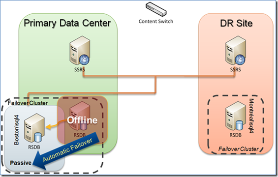
If the active server in the primary data center failover cluster goes offline, the active/passive setup of the SQL Server failover cluster will kick in. The active server will automatically fail over to the passive instance of the node with little to no service interruption. The report server may report that it cannot connect to the report server database, but after the passive node comes online, it will automatically re-establish the connection. All report server connectivity will continue as previously performed except that now the passive instance has become the active instance.

Figure 3: Active cluster for RSDB in the primary data center goes offline
Entire RSDB Cluster in the Primary Data Center Goes Offline
If the primary data center RSDB SQL Server cluster goes offline, the disaster recovery solution is to manually fail over to the RSDB on the disaster recovery site to continue serving up reports. But note that this is a manual failover process, which requires manual configuration of the Reporting Services servers in the Reporting Services farm to point to the RSDB instance within the disaster recovery site. It is important to be aware that, with asynchronous mirroring, manual failover by definition forces the service to allow data loss. With Reporting Services, however, the data loss should be minimal because report metadata is not frequently updated and snapshots can be re-created. By configuring the primary data center and disaster recovery site RSDBs with identical instance names (recall that both instances are named sql4 but that they are in different domains), the manual failover is simplified because the Reporting Services servers will connect to an identically named instance of the RSDB (different domain, but same name).

Figure 4: Entire cluster for RSDB in the primary data center goes offline
Primary Data Center Outage Scenarios
If the entire primary data center goes offline for either a planned or unplanned outage, the content switch will automatically fail over to the Reporting Services farm in the disaster recovery site, but you will need to perform a manual failover to ensure that the Reporting Services servers can connect to the copy of the RSDB in the disaster recovery site.
Planned Outages
For planned outages:
1) The content switch will perform the task of suspending the primary IP addresses and activating the DR site IP addresses so that all connections will be redirected to the disaster recovery site.
2) You will need to execute a script on the primary database to manually switch to the mirrored database. After the partner database becomes the primary, the same script can be re-executed to switch back to the original primary database. Here is an example:
— Script to manually fail over to the mirror database
— Example: switch from Boston\sql4 to Montreal\sql4
USE [master]
GO
— Database ReportingServer
ALTER DATABASE ReportingServer SET PARTNER FAILOVER
GO
Unplanned Outages
For unplanned outages:
1) The content switch will perform the task of suspending the primary IP addresses and activating the DR site IP addresses so that all connections will be redirected to the disaster recovery site.
2) You will need to run a manual failover script to force the service to switch with possible data loss. The script needs to run on the mirrored server in the case of loss of the principal server. Here is an example:
— Script to force database fail over of Boston\sql4 to Montreal\sql4
— in case of SQL Server instance failure
USE [master]
GO
— Database ReportingServer
ALTER DATABASE ReportingServer
SET PARTNER FORCE_SERVICE_ALLOW_DATA_LOSS
GO
After this script is run, the mirror server is the principal server and the mirror itself is suspended.
For more information about Reporting Services configuration for the database connection, see Configuring a Report Server Database Connection.
Break/Rebuild the Mirror
After the system goes down, it is undesirable to have the active system push data to the passive system (it cannot anyways). So it is important to break the mirror with the primary data center server and then re-establish it after the primary data center (in this example, Boston) server is back online. Note that the disaster recovery (in this example, Montréal) server is the one that is now active, so you will need to manually transfer the data from the DR site server back to the primary data center server (in this example, Montréal to Boston). To fully break the mirror, execute the following on the primary server:
ALTER DATABASE ReportingServer SET PARTNER OFF
RESTORE DATABASE ReportingServer WITH RECOVERY
To rebuild the mirror, follow the original steps in the Initializing Database Mirror section above.
Detail Logistics
It is important to understand that the Reporting Services report jobs, schedules, and subscriptions will not be mirrored between the RSDB from the primary data center and the disaster recovery site. This occurs because SQL Server Agent jobs are stored in the msdb database, which is not mirrored. A common method to resolve this issue is to script all of these Reporting Services jobs in the primary site and then use these scripts to re-create them on the disaster recovery site (with the jobs disabled); activate these jobs only if the system fails over. In the case of Reporting Services database migration, it is not necessary to perform this operation, as noted in How to: Migrate a Reporting Services Installation.
Note that logins created on the primary site may not be replicated to the disaster recovery site. To work around this problem, we recommend storing all of these logins into their own database and mirroring this database to the DR site as well. Then create a script to generate the logins within the DR site to re-establish the logins. For more information, see How to transfer logins and passwords between instances of SQL Server.
Conclusion
With these guidelines, you can prepare your Reporting Services environment for disaster recovery scenarios. The key here is that you will need to use a combination of hardware components, network connectivity, SQL Server database mirroring, and architecture to create a disaster recovery infrastructure to support an enterprise SQL Server Reporting Services environment. As noted, this case study has used specific techniques such as active/passive clustering and asynchronous database mirroring to support their disaster recovery requirements. Your situation may be different, but this technical note should provide you with the basic framework for Reporting Services disaster recovery. The hope is that you will never need to use it, but at least now you are ready in case you do.


